Purkinje like stimulation of a realistic BiV geometry#
In this example we will use a realistic geometry generated from the mean shape of an atlas from the UK Biobank of 630 healthy subjects. We will also stimulate it using a random activation pattern on the endocardial layer of the left and right ventricle.
import io4dolfinx
import numpy as np
import cardiac_geometries as cg
import dolfinx
import gotranx
import beat
import pyvista
from dolfinx.io import VTXMeshPolicy
logging.basicConfig(level=logging.INFO)
logger = logging.getLogger(__name__)
Initialize the MPI communicator and create a folder to store the results
comm = MPI.COMM_WORLD
results_folder = Path("results-ukb")
results_folder.mkdir(exist_ok=True)
Define the geometry which is created using the cardiac_geometries package. Now we create the geometry. If the geometry already exists, we just load it.
geodir = results_folder / "geo"
if not geodir.is_dir():
    cg.mesh.ukb(outdir=geodir, comm=comm, char_length_max=2.0, char_length_min=2.0)
INFO:ukb.atlas:Downloading https://www.cardiacatlas.org/share/download.php?id=60&token=AR3JSoaxJ9Ev9n8QAkvV4BHJUniyttqm&download to /github/home/.ukb/UKBRVLV.zip. This may take a while.
INFO:ukb.atlas:Done downloading.
INFO:ukb.atlas:Generating points from /github/home/.ukb/UKBRVLV.h5
INFO:ukb.atlas:Using mode -1 and std 1.5
INFO:ukb.surface:Saved results-ukb/geo/EPI_ED.stl
INFO:ukb.surface:Saved results-ukb/geo/MV_ED.stl
INFO:ukb.surface:Saved results-ukb/geo/AV_ED.stl
INFO:ukb.surface:Saved results-ukb/geo/TV_ED.stl
INFO:ukb.surface:Saved results-ukb/geo/PV_ED.stl
INFO:ukb.surface:Saved results-ukb/geo/LV_ED.stl
INFO:ukb.surface:Saved results-ukb/geo/RV_ED.stl
INFO:ukb.surface:Saved results-ukb/geo/RVFW_ED.stl
INFO:ukb.mesh:Creating mesh for ED with char_length_max=2.0, char_length_min=2.0
0
INFO:ukb.mesh:Created mesh results-ukb/geo/ED.msh
Info    : Reading 'results-ukb/geo/ED.msh'...
Info    : 27 entities
Info    : 24821 nodes
Info    : 128998 elements
Info    : [  0%] Reading elements
Info    : [ 10%] Reading elements
Info    : [ 20%] Reading elements
Info    : [ 30%] Reading elements
Info    : [ 40%] Reading elements
Info    : [ 50%] Reading elements
Info    : [ 60%] Reading elements
Info    : [ 70%] Reading elements
Info    : [ 80%] Reading elements
Info    : [ 90%] Reading elements

Info    : 8 parametrizations
Info    : [  0%] Processing parametrizations
Info    : [ 10%] Processing parametrizations
Info    : [ 20%] Processing parametrizations
Info    : [ 30%] Processing parametrizations
Info    : [ 40%] Processing parametrizations
Info    : [ 60%] Processing parametrizations
Info    : [ 70%] Processing parametrizations
Info    : [ 80%] Processing parametrizations
Info    : Done reading 'results-ukb/geo/ED.msh'
INFO:ldrb.ldrb:Calculating scalar fields
INFO:ldrb.ldrb:Compute scalar laplacian solutions with the markers:
lv: [1]
rv: [2]
epi: [7]
base: [5, 6, 4, 3]
INFO:ldrb.ldrb: Num vertices: 24821
INFO:ldrb.ldrb: Num cells: 90338
INFO:ldrb.ldrb: Apex coord: (46.92, -19.91, -28.38)
INFO:ldrb.ldrb:
Calculating gradients
INFO:ldrb.ldrb:Compute fiber-sheet system
INFO:ldrb.ldrb:Angles:
INFO:ldrb.ldrb:alpha:
 endo_lv: 60
 epi_lv: -60
 endo_septum: 60
 epi_septum: -60
 endo_rv: 60
 epi_rv: -60
INFO:ldrb.ldrb:beta:
 endo_lv: 0
 epi_lv: 0
 endo_septum: 0
 epi_septum: 0
 endo_rv: 0
 epi_rv: 0
geo = cg.geometry.Geometry.from_folder(comm, geodir)
mesh_unit = "mm"
V = dolfinx.fem.functionspace(geo.mesh, ("P", 1))
INFO:cardiac_geometries.geometry:Reading geometry from results-ukb/geo
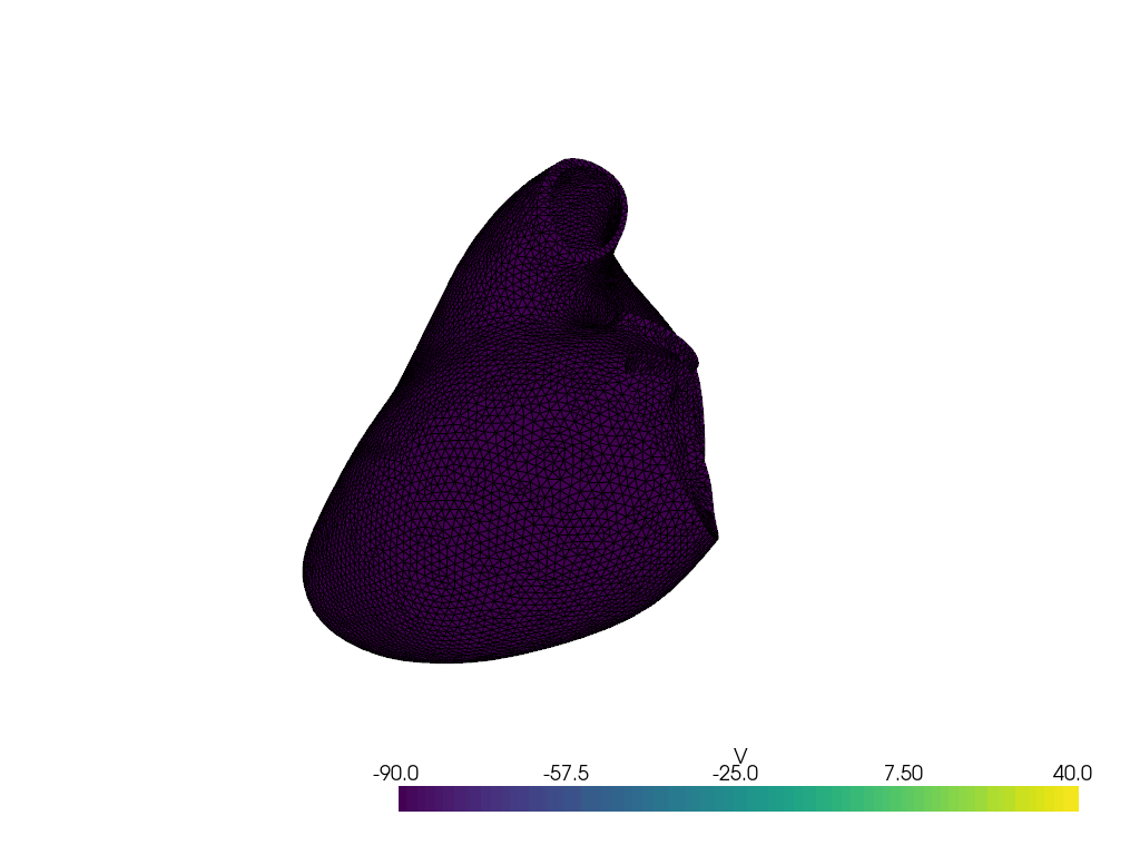
Let us plot the geometry
plotter_markers = pyvista.Plotter()
grid = pyvista.UnstructuredGrid(*dolfinx.plot.vtk_mesh(V))
plotter_markers.add_mesh(grid, show_edges=True)
plotter_markers.view_zy()
2026-07-06 12:39:16.699 ( 29.335s) [ 7F4D6A9EB140]vtkXOpenGLRenderWindow.:1458 WARN| bad X server connection. DISPLAY=
if not pyvista.OFF_SCREEN:
    plotter_markers.show()
else:
    plotter_markers.screenshot(results_folder / "mesh.png")
INFO:trame_server.utils.namespace:Translator(prefix=None)
INFO:wslink.backends.aiohttp:awaiting runner setup
INFO:wslink.backends.aiohttp:awaiting site startup
INFO:wslink.backends.aiohttp:Print WSLINK_READY_MSG
INFO:wslink.backends.aiohttp:Schedule auto shutdown with timout 0
INFO:wslink.backends.aiohttp:awaiting running future
Now we define the endocardial and epicardial markers. We use the expand_layer_biv function from the beat.utils module to create the markers. This will create a layer where 30% of the elements are endocardial, 30% are epicardial and the rest are midmyocardial. The reason for this is because we will apply different cellular models to the different layers representing the different cells in the different layers.
When creating the markers, we also specify the values of markers for the midmyocardial, endocardial and epicardial layers. These are used when we specify the cellular models for the different layers.
mid_marker = 0
endo_marker = 1
epi_marker = 2
endo_epi = beat.utils.expand_layer_biv(
    V=V,
    ft=geo.ffun,
    endo_lv_marker=geo.markers["LV"][0],
    endo_rv_marker=geo.markers["RV"][0],
    epi_marker=geo.markers["EPI"][0],
    endo_size=0.3,
    epi_size=0.3,
    output_mid_marker=mid_marker,
    output_endo_marker=endo_marker,
    output_epi_marker=epi_marker,
)
INFO:beat.utils:Expanding endo and epi markers to the rest of the mesh
Let us plot these markers
plotter_markers = pyvista.Plotter()
grid = pyvista.UnstructuredGrid(*dolfinx.plot.vtk_mesh(V))
grid.point_data["V"] = endo_epi.x.array
plotter_markers.add_mesh(grid, show_edges=True)
plotter_markers.view_zy()
if not pyvista.OFF_SCREEN:
    plotter_markers.show()
else:
    plotter_markers.screenshot(results_folder / "endo_epi.png")
Let us also save the markers to file which can be visualized in Paraview.
with dolfinx.io.XDMFFile(comm, results_folder / "endo_epi.xdmf", "w") as xdmf:
    xdmf.write_mesh(geo.mesh)
    xdmf.write_function(endo_epi)
Now we will run the the single cell simulations to obtain the steady states solutions which will be used as initial states for the full 3D simulation.
We will use the package gotranx to generate the generalized Rush Larsen scheme. Please see the following example if you want to learn how to generate the code from a cell model obtained from CellML.
The code for the ODE will be generated only if it does not exist.
print("Running model")
# Load the model
model_path = Path("ToRORd_dynCl_endo.py")
if not model_path.is_file():
    print("Generate code for cell model")
    here = Path.cwd()
    ode = gotranx.load_ode(here / ".." / "odes" / "torord" / "ToRORd_dynCl_endo.ode")
    code = gotranx.cli.gotran2py.get_code(
        ode,
        scheme=[gotranx.schemes.Scheme.generalized_rush_larsen],
    )
    model_path.write_text(code)
Running model
import ToRORd_dynCl_endo
model = ToRORd_dynCl_endo.__dict__
The steady state solutions are obtained by pacing the cells for a certain number of beat with a basic cycle length of 1000 ms. We will use 20 beats here but this should be increased to at least 200 beats for a real simulation. Let’s also use a time step of 0.05 ms for the single cell simulations a
dt = 0.05
nbeats = 20  # Should be set to at least 200
BCL = 1000  # Basic cycle length
Here we also track the voltage and the intracellular calcium concentration (track_indices) which is saved to a separate folder for each layer along with a plot. This is useful to see whether the steady state is reached.
Also note that in the ToRORd cell model there is a parameter called celltype which is set to 0 for endocardial cells, 1 for epicardial cells and 2 for midmyocardial cells. This is used to set the different parameters for the different cell types.
celltype_mid = 2
celltype_endo = 0
celltype_epi = 1
Now, let us get the steady states for the different layers.
print("Get steady states")
init_states = {
    mid_marker: beat.single_cell.get_steady_state(
        fun=model["generalized_rush_larsen"],
        init_states=model["init_state_values"](),
        parameters=model["init_parameter_values"](celltype=celltype_mid),
        outdir=results_folder / "mid",
        BCL=BCL,
        nbeats=nbeats,
        track_indices=[model["state_index"]("v"), model["state_index"]("cai")],
        dt=dt,
    ),
    endo_marker: beat.single_cell.get_steady_state(
        fun=model["generalized_rush_larsen"],
        init_states=model["init_state_values"](),
        parameters=model["init_parameter_values"](celltype=celltype_endo),
        outdir=results_folder / "endo",
        BCL=BCL,
        nbeats=nbeats,
        track_indices=[model["state_index"]("v"), model["state_index"]("cai")],
        dt=dt,
    ),
    epi_marker: beat.single_cell.get_steady_state(
        fun=model["generalized_rush_larsen"],
        init_states=model["init_state_values"](),
        parameters=model["init_parameter_values"](celltype=celltype_epi),
        outdir=results_folder / "epi",
        BCL=BCL,
        nbeats=nbeats,
        track_indices=[model["state_index"]("v"), model["state_index"]("cai")],
        dt=dt,
    ),
}
INFO:beat.single_cell:Computing steady state with 20 beats.
Get steady states
INFO:beat.single_cell:Computing steady state with 20 beats.
INFO:beat.single_cell:Computing steady state with 20 beats.
The initial states are now obtained and we can use these to set the initial states for the full 3D simulation. We will also set the parameters for the different layers. We also need to ensure that the stimulus amplitude in the single cell simulations is set to 0.0 as we will apply the stimulus in the 3D simulation.
parameters = {
    mid_marker: model["init_parameter_values"](
        i_Stim_Amplitude=0.0,
        celltype=celltype_mid,
    ),
    endo_marker: model["init_parameter_values"](
        i_Stim_Amplitude=0.0,
        celltype=celltype_endo,
    ),
    epi_marker: model["init_parameter_values"](
        i_Stim_Amplitude=0.0,
        celltype=celltype_epi,
    ),
}
We also need to specify the function to be used for the ODE solver for the different layers. If you plan to run a long running simulation you might consider jit compiling the function using Numba. In this example we will not do that but you can do it by uncommenting the line below.
import numba
# f = numba.jit(model["generalized_rush_larsen"], nopython=True)
f = model["generalized_rush_larsen"]
fun = {
    mid_marker: f,
    endo_marker: f,
    epi_marker: f,
}
We also need to specify the index of the state variable v in the state vector. This is because the voltage appear in both the ODE and and PDE and the solution has be passed between the two solvers.
v_index = {
    mid_marker: model["state_index"]("v"),
    endo_marker: model["state_index"]("v"),
    epi_marker: model["state_index"]("v"),
}
Now let us specify the conductivities and membrane capacitance. The conductivities are set to the default values for the Bishop model. The membrane capacitance is set to 1 uF/cm^2.
chi = 1400.0 * beat.units.ureg("cm**-1")
s_l = 0.24 * beat.units.ureg("S/cm")
s_t = 0.0456 * beat.units.ureg("S/cm")
s_l = (s_l / chi).to("uA/mV").magnitude
s_t = (s_t / chi).to("uA/mV").magnitude
# dim = geo.mesh.topology().dim()
M = s_l * ufl.outer(geo.f0, geo.f0) + s_t * (
    ufl.Identity(3) - ufl.outer(geo.f0, geo.f0)
)
C_m = 1.0 * beat.units.ureg("uF/cm**2")
Now we will create a random activation pattern on the endocardial layer of the left and right ventricle. First we define a time variable and set a seed for the random number generator to ensure reproducibility.
time = dolfinx.fem.Constant(geo.mesh, dolfinx.default_scalar_type(0.0))
np.random.seed(0)
We will stimulate 900 points on the endocardial layer, and we do this by first finding the facets on the endocardial layer and then selecting 900 random points on these facets.
num_points = 900
lv_endo_facets = geo.ffun.find(geo.markers["LV"][0])
rv_endo_facets = geo.ffun.find(geo.markers["RV"][0])
endo_facets = np.concatenate([lv_endo_facets, rv_endo_facets])
Distribute the requested number of stimulus points over MPI ranks.
local_num_endo_facets = len(endo_facets)
all_num_endo_facets = comm.allgather(local_num_endo_facets)
total_num_endo_facets = sum(all_num_endo_facets)
if total_num_endo_facets < num_points:
    raise RuntimeError(
        "Not enough endocardial facets to select "
        f"{num_points} stimulus points. "
        f"Only found {total_num_endo_facets} facets globally.",
    )
Distribute the total number of stimulus points across MPI ranks proportional to the number of local endocardial facets
raw_counts = [
    num_points * n / total_num_endo_facets
    for n in all_num_endo_facets
]
Round down to get integer point counts. This will likely result in some points being unassigned due to rounding down, which we will handle in the next step.
stim_counts = [int(np.floor(count)) for count in raw_counts]
Add the remaining points to the ranks with the largest fractional parts so that the global number of stimulus points is exactly num_points.
missing = num_points - sum(stim_counts)
Compute the fractional parts of the proportional counts. Ranks with the largest fractional parts are the ones that were closest to receiving one extra point before rounding down.
fractions = [
    raw_counts[i] - stim_counts[i]
    for i in range(len(stim_counts))
]
for i in np.argsort(fractions)[::-1][:missing]:
    stim_counts[i] += 1
Number of stimulus points assigned to this rank.
local_num_points = stim_counts[comm.rank]
np.random.seed(1234 + comm.rank)
np.random.shuffle(endo_facets)
endo_facets_stim = endo_facets[:local_num_points]
midpoints = dolfinx.mesh.compute_midpoints(geo.mesh, 2, endo_facets_stim)
We will stimulate the cells with a current of 2.5 uA/cm^2 for 2 ms starting at 0 ms. The points will be activated with some delay which is a random number between 0 and 4 ms.
start = 0.0
duration = 2.0
value = 2.5
activation_duration = 4.0
delays = np.random.uniform(0, activation_duration, local_num_points)
logger.info(
    "[rank %d] endo_facets=%d, stim_points=%d, delays=%d",
    comm.rank,
    len(endo_facets),
    len(midpoints),
    len(delays),
)
INFO:__main__:[rank 0] endo_facets=19667, stim_points=900, delays=900
We now generate the expression for the stimulation. Here we also specify a tolerance of 1.0 which means that the stimulation will be applied to points that are within 1.0 mm of the midpoints.
stim_expr = beat.stimulation.generate_random_activation(
    mesh=geo.mesh,
    time=time,
    points=midpoints,
    delays=delays,
    stim_start=start,
    stim_duration=duration,
    stim_amplitude=value,
    tol=1.0,
)
Finally we will create the stimulus function which will be used to apply the stimulus to the cells.
W = dolfinx.fem.functionspace(geo.mesh, ("DG", 0))
stim = dolfinx.fem.Function(W)
We also create an expression that will be used to update the stimulus at each time step.
stim_update_expr = dolfinx.fem.Expression(stim_expr, beat.utils.interpolation_points(W))
Now we are ready to create the PDE solver.
pde = beat.MonodomainModel(
    time=time,
    mesh=geo.mesh,
    M=M,
    I_s=stim,
    C_m=C_m.to(f"uF/{mesh_unit}**2").magnitude,
)
and the ODE solver. Here we also need to specify which space to use for the ODE solver. We will use first order Lagrange elements, which will solve one ODE per node in the mesh.
V_ode = dolfinx.fem.functionspace(geo.mesh, ("P", 1))
ode = beat.odesolver.DolfinMultiODESolver(
    v_ode=dolfinx.fem.Function(V_ode),
    v_pde=pde.state,
    markers=endo_epi,
    num_states={i: len(s) for i, s in init_states.items()},
    fun=fun,
    init_states=init_states,
    parameters=parameters,
    v_index=v_index,
)
We will the the ODE and PDE using a Godunov splitting scheme. This will solve the ODE for a time step and then the PDE for a time step. This will be repeated until the end time is reached.
solver = beat.MonodomainSplittingSolver(pde=pde, ode=ode)
We will also save the results with VTX for visiualization in Paraview and the checkpoint file for retrieving the results later. Here we use the io4dolfinx package.
vtxfname = results_folder / "v.bp"
checkpointfname = results_folder / "v_checkpoint.bp"
Make sure to remove the files if they already exist
shutil.rmtree(vtxfname, ignore_errors=True)
shutil.rmtree(checkpointfname, ignore_errors=True)
vtx = dolfinx.io.VTXWriter(
    comm,
    vtxfname,
    [solver.pde.state],
    engine="BP4",
    mesh_policy=VTXMeshPolicy.reuse,
)
io4dolfinx.write_mesh(checkpointfname, geo.mesh)
Let’s create a function to be used to save the results. This will save the results to the VTX file and the checkpoint file.
plotter_voltage = pyvista.Plotter()
viridis = plt.get_cmap("viridis")
grid.point_data["V"] = solver.pde.state.x.array
grid.set_active_scalars("V")
renderer = plotter_voltage.add_mesh(
    grid,
    show_edges=True,
    lighting=False,
    cmap=viridis,
    clim=[-90.0, 40.0],
)
gif_file = Path("ukb_purkinje_sim.gif")
gif_file.unlink(missing_ok=True)
plotter_voltage.open_gif(gif_file.as_posix())
def save(t):
    v = solver.pde.state.x.array
    print(f"Solve for {t=:.2f}, {v.max() =}, {v.min() =}")
    vtx.write(t)
    io4dolfinx.write_function(checkpointfname, solver.pde.state, time=t, name="v")
    grid.point_data["V"] = solver.pde.state.x.array
    plotter_voltage.write_frame()
We will save results every 1 ms
save_every_ms = 1.0
save_freq = round(save_every_ms / dt)
And we will run the simulation for 10 ms (one beat is 1000 ms so you would typically run for at least 1000 ms)
end_time = 10.0
t = 0.0
i = 0
while t < end_time + 1e-12:
    # Make sure to save at the same time steps that is used by Ambit

    if i % save_freq == 0:
        save(t)

    # We also make sure to update the stimulus at the correct time

    stim.interpolate(stim_update_expr)
    solver.step((t, t + dt))
    i += 1
    t += dt
Solve for t=0.00, v.max() =np.float64(-89.45964555210824), v.min() =np.float64(-89.80955482958359)
Solve for t=1.00, v.max() =np.float64(-59.632362120278316), v.min() =np.float64(-90.78937727859497)
Solve for t=2.00, v.max() =np.float64(14.050711745691212), v.min() =np.float64(-90.42183665071266)
Solve for t=3.00, v.max() =np.float64(47.80420992683374), v.min() =np.float64(-90.24855415961768)
Solve for t=4.00, v.max() =np.float64(71.7009767738325), v.min() =np.float64(-89.85317509966727)
Solve for t=5.00, v.max() =np.float64(65.85279698482069), v.min() =np.float64(-89.42555510582115)
Solve for t=6.00, v.max() =np.float64(50.055655786342825), v.min() =np.float64(-96.55336004636749)
Solve for t=7.00, v.max() =np.float64(33.992571277759005), v.min() =np.float64(-90.20203635385519)
Solve for t=8.00, v.max() =np.float64(33.93701070643984), v.min() =np.float64(-92.51976746918332)
Solve for t=9.00, v.max() =np.float64(35.799706262192196), v.min() =np.float64(-93.25174982362289)
Solve for t=10.00, v.max() =np.float64(35.41930656580657), v.min() =np.float64(-91.27757526867954)
plotter_voltage.close()
# -